
Introduction
Graphics card repair requires a systematic approach to identify the actual cause of a fault. When a graphics card has a missing power rail, the problem may originate from the power controller, MOSFETs, capacitors, feedback circuitry, or another component in the associated power circuit. Rather than replacing components randomly, checking the power rails and the controller's important signals can help narrow down the fault.
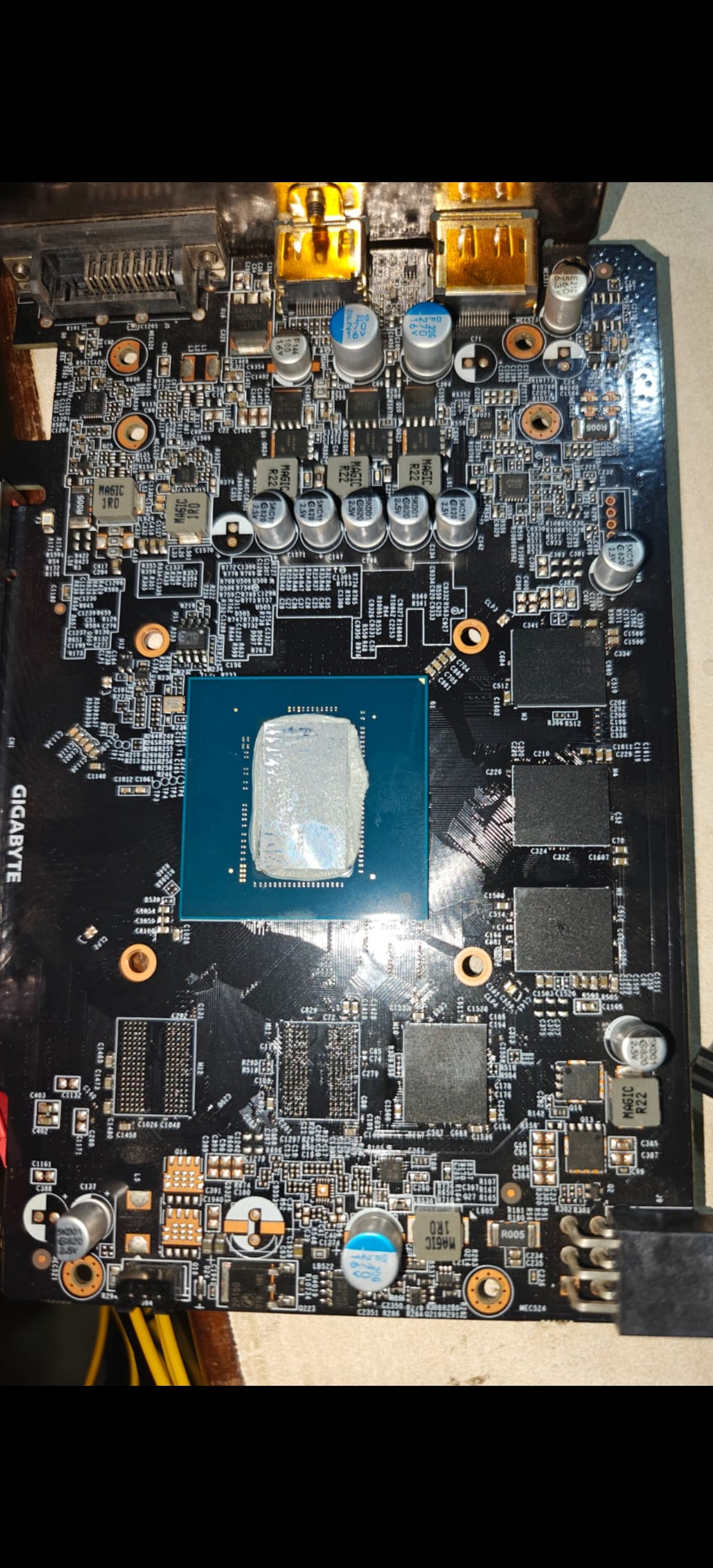
In this repair case, we worked on a Gigabyte GTX 1650, model GV-N1656D6-4GD, PCB Revision 2.0, which had a missing VRAM power supply. The memory power rail, also called VMEM or FBVDDQ, was measuring 0 V, even though several other important power rails were present.
Our initial measurements showed that the 12 V input, 3.3 V rail, and 1.8 V rail were available. The GPU core voltage was approximately 0.7 V, and the PEX rail measured approximately 1.0 V. However, the VMEM output remained at 0 V, preventing the memory power circuit from receiving its required supply.
We used the BoardView to trace the FBVDDQ circuit and checked the important signals on the VMEM power controller. The controller had its 5 V input supply, its enable signal was investigated, and the Power Good signal appeared normal. However, we observed no switching activity at the controller's PHASE/SW output while the VMEM rail remained at 0 V.
We also checked the relevant MOSFETs, including Q13 and Q16, and considered them to be in good condition based on our testing. The investigation ultimately led us to the defective power controller marked 88 EH, identified as the RT8237E in our repair notes.
After replacing the controller, the missing VMEM voltage issue was resolved.
This article documents the actual troubleshooting process, the measurements that guided the diagnosis, and the final repair result.
1. Understanding the Initial Problem
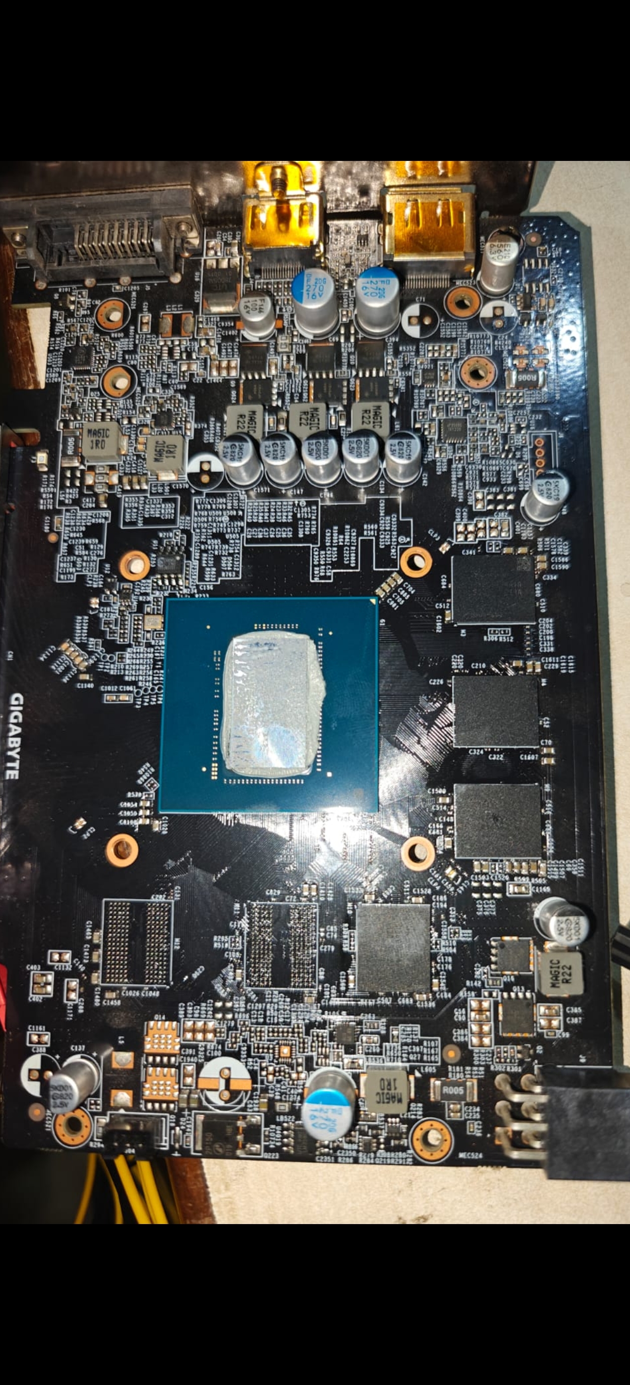
The first step in this repair was to establish the condition of the graphics card's power rails. Before investigating individual components, we needed to determine whether the board had a general power failure or whether a particular power supply was missing.
Graphics cards use multiple voltage rails to power different sections of the board. The main input supplies power to the board's power-conversion circuits, while auxiliary rails and dedicated regulators supply the GPU core, memory, PCIe interface, and other circuitry.
A fault in one of these supplies can prevent the corresponding section from operating correctly, even when the other rails are present.
In our case, the most important symptom was the absence of the VRAM power supply. The expected FBVDDQ output for this circuit was approximately 1.35 V, but the faulty board measured 0 V.
Initial power-rail measurements
We checked the available power rails using a digital multimeter. The initial results were:
| Power rail | Measured result | Observation |
|---|---|---|
| 12 V input | Present | Main input power available |
| 3.3 V | Present | Auxiliary power rail available |
| 1.8 V | Present | Auxiliary power rail available |
| VCore | 0.7 V | GPU core voltage present |
| PEX | 1.0 V | PEX voltage present |
| VMEM / FBVDDQ | 0 V | Memory power supply missing |
The presence of 12 V, 3.3 V, and 1.8 V showed that the board was receiving its main input power and that several auxiliary supplies were available. VCore and PEX were also present.
However, VMEM was completely absent.
This was the key observation that directed our investigation. Instead of treating the card as having a complete power failure, we focused on the circuit responsible for generating the memory voltage.
Why the missing VMEM rail mattered
The VMEM rail supplies the graphics card's video memory circuitry. The memory devices require their specified operating voltage to function correctly. If the supply is missing, the VRAM cannot operate normally, and the graphics card may fail to initialize.
The fact that VCore was present did not mean that the GPU was fully operational. Similarly, the presence of PEX did not confirm that every required power rail was functioning.
We therefore concentrated on the FBVDDQ circuit and its power controller.
The diagnostic objective was straightforward: determine why the VMEM circuit was not producing its expected output voltage.
2. Using BoardView to Trace the VMEM Circuit
Once we confirmed that VMEM was missing, we opened the GV-N1656D6-4GD Rev 2.0 BoardView to trace the relevant power circuit.
BoardView is an important tool in component-level graphics card repair because it provides information about component designators, pin connections, and electrical nets. Instead of guessing which components belong to a particular circuit, we can trace the connections and identify the components associated with the missing voltage.
One of the important nets we investigated was:
PS_FBVDDQ_PHASE1
This switching-phase net connects to several components in the memory power circuit. The BoardView helped us identify the relevant MOSFETs, inductor, capacitors, and other connected components.
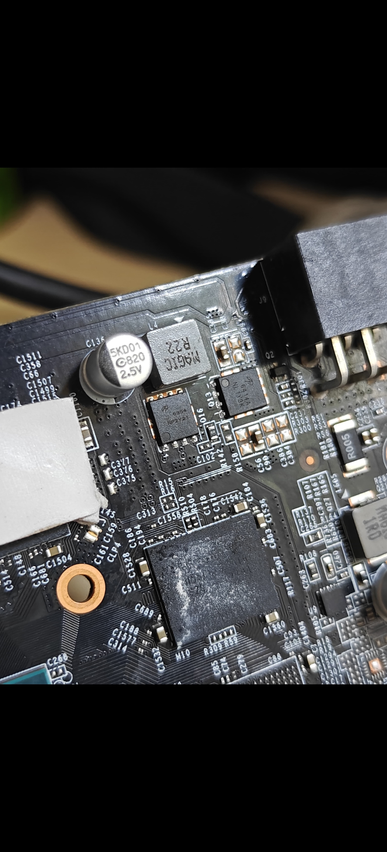
We examined the connections associated with components such as Q13, Q16, L4, C263, and other components listed on the switching-phase net.
However, a component appearing in a BoardView net list does not automatically mean that it is defective. A switching-phase net is part of the converter's electrical path, and several components can be connected to it.
The purpose of using BoardView was to understand the circuit and identify the correct points for measurement.
Why we focused on the controller
The VMEM circuit contains a power controller that manages the switching operation required to generate the memory supply. The controller works with the switching stage to convert the available input power into the required output voltage.
If the controller does not operate correctly, the output rail may remain at 0 V even when the board has its other power supplies.
After tracing the circuit, we moved on to checking the controller's input supply, enable signal, Power Good signal, and switching output.
These measurements provided a direct way to investigate whether the controller was receiving power and whether its switching operation was occurring.
3. Checking the MOSFETs
Before replacing the power controller, we investigated the MOSFETs associated with the VMEM switching circuit.
The relevant components included Q13 and Q16. We performed measurements on these components and compared readings where appropriate with a working board.
During the investigation, we measured Q13 between pin 5 and pin 1 in diode mode. The reading was approximately 0.573 V in one probe orientation and approximately 1.500 kΩ in the reverse direction.
We also measured resistance from relevant Q13 pins to ground. These readings helped us understand the circuit, but in-circuit measurements must be interpreted carefully because the surrounding components can influence the results.
A MOSFET should not be considered defective simply because the memory power rail is missing. Likewise, an in-circuit continuity beep or an unexpected resistance reading does not necessarily establish that the MOSFET is shorted.
We used our measurements and comparison checks to assess the condition of the relevant MOSFETs.
Based on our testing, we considered Q13 and Q16 to be in good condition. We therefore did not identify them as the confirmed cause of the missing VMEM supply.
This was an important part of the diagnosis. Rather than replacing the switching MOSFETs without sufficient evidence, we continued investigating the component responsible for controlling the switching operation.
4. Checking the VMEM Controller Signals
With VMEM still measuring 0 V and the relevant MOSFETs considered good, we focused on the VMEM power controller.
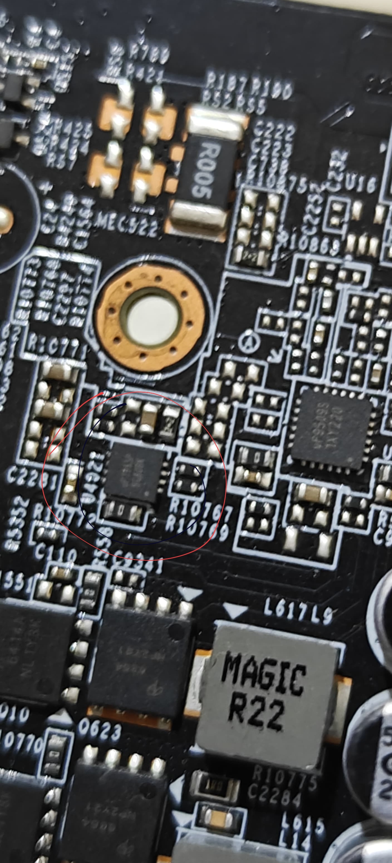
The controller was marked 88 EH and identified as the RT8237E in our repair notes.
The important part of this stage was checking the controller's key signals with a multimeter. We wanted to establish whether the IC had its input supply, whether it was receiving an enable signal, whether the Power Good signal appeared normal, and whether switching activity was present at the output.
The following controller checks guided our diagnosis.
VIN — Pin 7
The controller's input supply was checked first.
We measured approximately 5 V at pin 7, confirming that the expected 5 V supply was present at this pin.
This was an important observation because a power controller cannot operate correctly without its required supply voltage. Since the 5 V input was available, we continued checking the controller's other signals rather than treating the missing VMEM voltage as an input-supply problem.
EN (Enable) — Pin 3
Next, we checked the enable signal at pin 3.
The enable signal determines whether the controller is being commanded to operate. For this circuit, the expected enable level was approximately 3 V.
Checking this pin was important because a controller may remain inactive if its enable condition is not satisfied. In our troubleshooting, the enable signal was investigated alongside the input supply and the other controller signals.
With the 5 V input present, we continued to the Power Good and switching-output checks.
PGOOD (Power Good) — Pin 1
We also checked the controller's PGOOD signal at pin 1.
The Power Good signal is used to indicate the status of the relevant power supply according to the controller's operating conditions. Its meaning must be interpreted in the context of the particular controller and circuit.
During our diagnosis, the PGOOD signal appeared normal. This was another useful observation as we narrowed down the problem.
PHASE / SW — Pin 8
The most important finding came from checking the switching output at pin 8, PHASE/SW.
While the VMEM rail remained at 0 V, we observed no switching activity at this output using our available multimeter.
A digital multimeter cannot display switching waveforms in the same way as an oscilloscope, so a zero or unchanging reading alone cannot prove that no switching pulses exist. Nevertheless, in our particular repair, the lack of observed switching activity, together with the missing VMEM output and the other controller checks, was the key clue that led us to suspect the controller.
The diagnosis was based on the overall pattern of measurements rather than one pin in isolation:
- The main input and auxiliary power rails were present.
- VCore and PEX were present.
- VMEM remained at 0 V.
- The controller's 5 V input was present.
- The enable and Power Good signals were investigated and appeared satisfactory for our diagnosis.
- No switching activity was observed at the PHASE/SW output.
- The relevant MOSFETs had been checked and were considered good.
Taken together, these observations directed us toward the VMEM controller itself.
5. Identifying the Faulty 88 EH Controller
After the power-rail checks, BoardView tracing, MOSFET testing, and controller-signal measurements, we identified the VMEM power controller as the suspected faulty component.
The IC carried the marking 88 EH. In our repair notes and the replacement listing, it was identified as an RT8237E power controller.
The controller is responsible for managing the switching operation used to generate the memory supply. When the controller fails to operate correctly, the switching stage may not generate the required output voltage.
This was consistent with the condition we observed: the board had several functioning power rails, but the VMEM output remained at 0 V and no switching activity was observed at the controller's PHASE/SW output.
The diagnosis was therefore based on the actual measurements obtained during the repair, rather than simply assuming that the controller was defective because the memory voltage was missing.
We decided to replace the suspected faulty controller and then verify whether the original fault condition changed.
Replacement IC reference
The replacement component listing we used as a reference is available here:
88 EH / RT8237E Power Controller — CTLabBD
The “88 EH” marking is included because that is the marking relevant to this repair. When sourcing replacement ICs, the complete part number, package, pinout, and electrical compatibility should be verified rather than relying on a short top marking alone.
6. Replacing the Faulty VMEM Controller IC
After identifying the controller as the suspected cause, we proceeded with its replacement.
Power-controller replacement requires care because the IC is soldered directly to the PCB and has small connections to surrounding circuitry. Excessive heat, incorrect orientation, or mechanical force can damage PCB pads and nearby components.
The replacement process involved removing the faulty controller, preparing and inspecting the PCB pads, and installing the replacement IC in the correct orientation.
After soldering, the area should be inspected for solder bridges, disturbed components, or damaged pads before power is applied again.
Once the replacement was completed, we powered the graphics card and checked the previously missing memory power supply.
The purpose of this test was to determine whether replacing the controller had restored the output that was missing during the original diagnosis.
7. Final Result: VMEM Voltage Restored
The repair was successful.
After replacing the faulty 88 EH controller, the no-VMEM-voltage issue was resolved. The memory power supply that had previously measured 0 V was restored.
This result supported the diagnosis that the defective controller was responsible for the missing memory voltage in this case.
The repair also demonstrated the importance of checking the controller's key signals before replacing other components. Although the missing VMEM supply could initially have pointed toward several parts of the switching circuit, our measurements led us to investigate the controller after the relevant MOSFETs had been checked.
Rather than replacing Q13 and Q16 without evidence, we concentrated on the controller's input supply, enable signal, Power Good status, and switching output. The successful replacement resolved the original fault.
The confirmed result of this repair was the restoration of VMEM. Further validation of a repaired graphics card can include checking that the voltage remains stable, confirming that the card initializes correctly, and performing functional tests.